
|
The Mitsubishi Pajero Owners Club®
The Mitsubishi Pajero, Shogun, Montero, Challenger, Raider and EVO 4x4 Owner's Club
|
| View previous topic :: View next topic |
| Author |
Message |
fmiles
****

Age: 54
Zodiac: 
Joined: 19 Apr 2006
Posts: 282
Location: Hayling Island
|
 Posted: Wed Jan 23, 2008 15:25 Post subject: Instructions: How to Refurbish a Glow Plug Relay Posted: Wed Jan 23, 2008 15:25 Post subject: Instructions: How to Refurbish a Glow Plug Relay |
 |
|
I have learned a lot from folk off this forum, guess its time to help out!
If you have problems with your glow plug relay, it could be a small number of things.
1) Control feed to the relay not present - Thats a GlowPlug ECU issue, and a different story!
To check, get someone to turn on the ignition while you measure for 12V+ on the control terminal (Smaller terminal on the side)
If feed is present, you will hear a healthy click anyway.
2) No live Feed to Relay
After measuring for 12V on Feed terminal, and its not there, its gotta be a fuse!
3) The Relay itself is defective.
Either the contacts have completely burned away (Internal investigation) or..
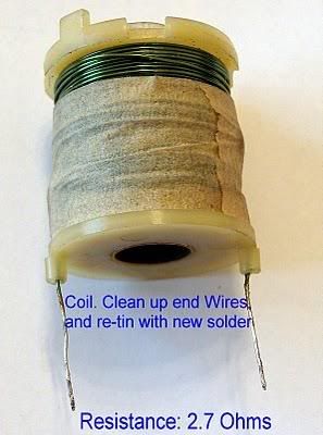
The Coil has burned and become open circuit (Disconnect cable, and measure resistance. You should get 2.7 Ohms) or..
You are suffering from Dry Solder joints on the top cap (Inspect for deterioration. Good solder should not be hazed)
If its an internal investigation, do as follows:
1) IMPORTANT: When you disconnect the nuts holding the Feed and Supply Cables (#10), PLEASE watch where your wrench goes! It gets uncomfortably close to chassis ground, and you risk blowing a fuse or two.
2) Before you bend the cables out of the way, please tie them together and insulate them all. I didnt, and had fireworks (these chaps are LIVE)
3) Take the 4 screws out, and carefully prise the main body from the top half. It will separate, its just the rubber seal that sticks a bit. Dont worry, you are in no danger or ripping or breaking anything, the bottom can part is completely separate.
All The Bits :
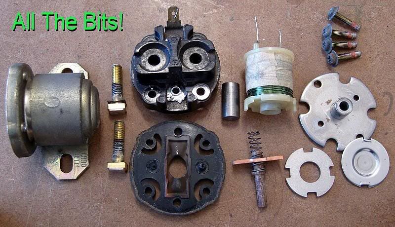
4) Next you need to remove the Coil :
This is the fiddly bit, and Needs careful solder removal from the top cap. If you are a dab hand at solder removal, skip to step 5 after doing your stuff.
Gently, put the coil in a vice. You just want to hold it, not crush it! this will allow you to gently pull the top half off
When you put your iron on the old solder, its sometimes difficult to get it to melt. Simply 'Add' fresh solder,and this will provide a better surface to contact. Get all the solder melted, on one contact, and pull gently. You will feel the wire slipping. Now move to the other side, and do the same. The top should separate after 4 or 5 cycles of this. Please do not yank too hard!
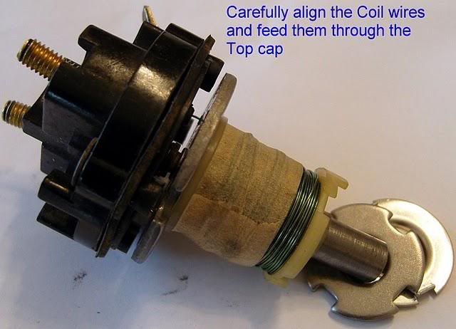
The Relay Coil :
5) After Separating all bits, carefully clean all contact surface with Wire wool or high grade Wet'n'Dry paper, about 600 grit. Make sure you dont touch the surfaces, grease isnt a good conductor
Clean the contacts :
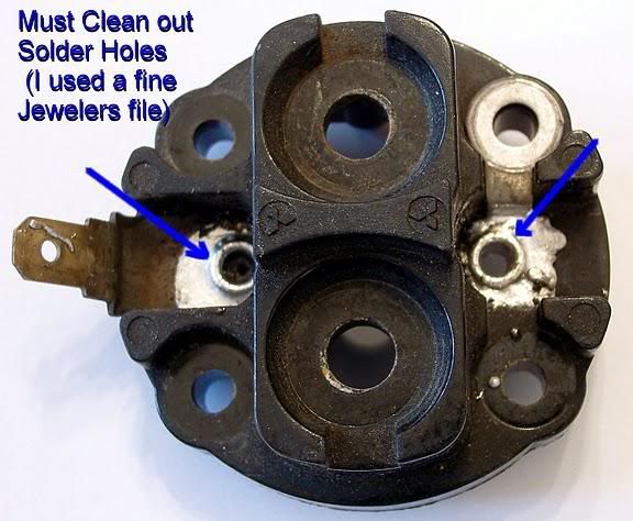
6) Remove excess solder from the holes, by heating up, and tapping the Top Cap. This will splash hot solder all over your brand new high heels  so be careful!. Clean the holes with a fine file if you feel inclined to do so. so be careful!. Clean the holes with a fine file if you feel inclined to do so.
Clean the Solder Holes :
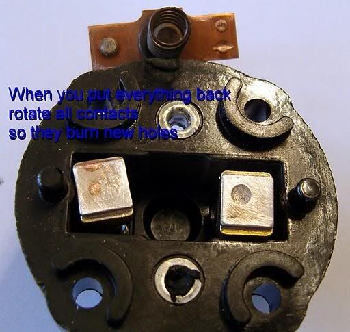
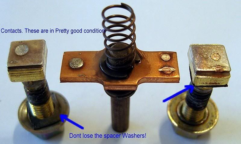
7) When reassembling, turn the Copper Contact bar around, so they burns fresh holes.
Copper Bar :
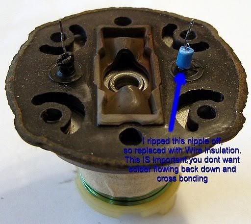
If you end up ripping the rubber nipple that goes into the hole, simply use insulation from a bit of wire
Insulation :
8) Screw everything together, and once all assembled, reflow new solder into the solder holes around the wires. dont hold it too long, solder has a habit of crawling down into places it doesnt belong. DO NOT BLOW on the solder joint, it will fatigue it, resulting in a dry joint!
9) If you have a 21V Battery with Leads, and a meter, test the relay. connect the case to negative, and apply 12V to the control (Dont hold it on for too long). Relay should click. Meter of course set to conductivity mode, connects to terminal to check for short.
Quick-start schematic :
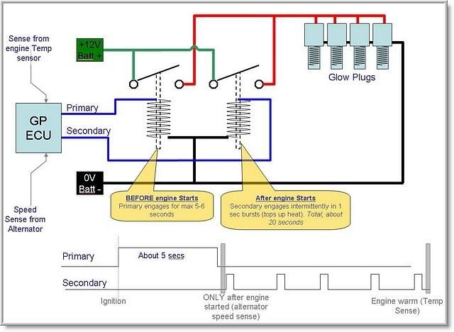
Standard Alternator Schematic :
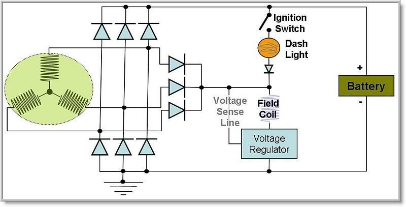
Alternators wont generate charge without current in the field coil. Thats what the Voltage regulator does, measures for correct voltage, then cuts the current through the field coil. |
|
| Back to top |
|
 |
Google
Sponsor

|
| Posted: Wed Jan 23, 2008 15:25 Post subject: Google Ads keep the POCUK free to join! |
|
|
|
|
| Back to top |
|
|
|
|
|
You cannot post new topics in this forum
You cannot reply to topics in this forum
You cannot edit your posts in this forum
You cannot delete your posts in this forum
You cannot vote in polls in this forum
You cannot attach files in this forum
You cannot download files in this forum
|
|

