
|
The Mitsubishi Pajero Owners Club®
The Mitsubishi Pajero, Shogun, Montero, Challenger, Raider and EVO 4x4 Owner's Club
|
| View previous topic :: View next topic |
| Author |
Message |
schweps
**

Age: 51
Zodiac: 
Joined: 29 Nov 2009
Posts: 101
Location: Turkiye
|
 Posted: Tue Oct 19, 2010 13:21 Post subject: Variable Shock Absorbers Posted: Tue Oct 19, 2010 13:21 Post subject: Variable Shock Absorbers |
 |
|
Hi,
I'd like to restore the electric shockers on my vehicle. Here is a brief summary about the existing situaiton.
I already have the switch on the panel just behind the handbrake and "S", "M" and "H" signs on the dashboard as well. Actually none of those three leds gives signal at the moment. I checked the fuse, it was ok. Is there anyway to check the Variable Shock Absorber Control Unit whether it is alive or dead? A while ago, during some electrical system check, i remember the leds came up and gone again. So the leds are fine but no signal recieving. The original absorbers were gone but the seller gave me all 4 actuators when i baught this vehicle. And last week i found a set of used suitable shock absorbers (without actuators on the top of them but with brackets) for reasonable price. The garage that i found them guaranteed that they work properly and they aren't blown out. Is there any test method to find out they are really in good condition. They have no sign about oil leakage.
When i compress them verticaly, with one end on the floor, i can hear some hydraulic passage voices during the travel. Could it be a sign? After i left all four shock absorbers compressed, i found one of them has extended to its earlier length but the other three stayed at their compressed length. But when i tried to extend them some of them gave response and decompressed accordingly to a length and stoped. Could it be a sign?
I also did some test on the existing actuators (motors). I cleaned them up and unscrewed the plastic cover. Enclosed picture You can see the inside view of the motor. When i jump the pins with my drill's 12v battery, the motor gives reaction. Then i screwed the cover back before the test. My main aim was to determine the revolution (or the angle) between three position of the switch and i had a chance to learn the way it works with this test. While jumping one pole ( I don't remember which) of the battery with a wire to the "red" cable pin of the motor, with another wire coming from the opposite pole of the battery, i was touching it to the other three pins (blue, green, yellow).
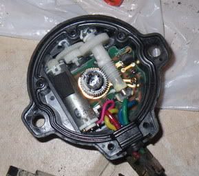
Let me explain what i have observed. First of all, the motor always turns at the same direction. Inside the (-) shaped hole on the output plastic shaft i put a "L" shape wire and watched the position while running the motor with different cables. With blue cable connection, the "L" shape sign shows direction "12" o'clock, with green cable connection it shows the direction "6" o'clock. In other words, these two position has 180 degree variation and these positions can not been effected according to the sequence. But with yellow cable connection it shows the direction "3" or "9" o'clock which depends on the sequence.
For more details; assume that the sign shows "3" o'clock and when i establish the connection of battery with motor through red and blue cables, shaft turns 270 degree and stops at 12 o'clock position. If i connect them through red and green, shaft turns 180 degree and stops at 6 o'clock position. If i have chose the yellow (instead of green) it would have turned 90 degree and stoped at 3 o'clock. If at 6 o'clock position a connection through red and yellow would cause shaft to turn 90 degree and stop at 9 o'clock position. After all my conclusion is that, there is some kind of distribution orifis plate on the piston and a big hole for soft mode, a small hole at the opposite side (180 degree) for hard mode and two medium sized holes 90 degree apart from the other two holes for medium mode.These 4 holes should be placed at the same circle.
Please treat kindly about this message cause it's even quite complicated subject to write on my own language as you may agree.
The pin you can see on the picture can easily turn to each direction and i don't know the exact position of distribution plate or whatever it might be. Is there any reference point that i should consider? If i connect the motor to the bracket with the pins any position i guess eventually medium mode would work properly but i'm afraid shocker might behave opposite at hard and soft modes. It would be very easy to change the motor position i guess but my main concern is if i couldn't notice the difference between modes.
There might be something that i'm wrong or missed so if i could have the assembled photo of each shock absorber taken from any of your vehicle, guys and gals, it would be wonderful.
Cheers,
Senol. |
|
| Back to top |
|
 |
Google
Sponsor

|
| Posted: Tue Oct 19, 2010 13:21 Post subject: Google Ads keep the POCUK free to join! |
|
|
|
|
| Back to top |
|
|
Scuftmuppet
*****

Age: 60
Zodiac: 
Joined: 03 Jun 2010
Posts: 981
Location: Thame Oxfordshire
|
| Posted: Tue Oct 19, 2010 15:55 Post subject: |
|
|
When you fit the shocks they are handed offside and nearside,
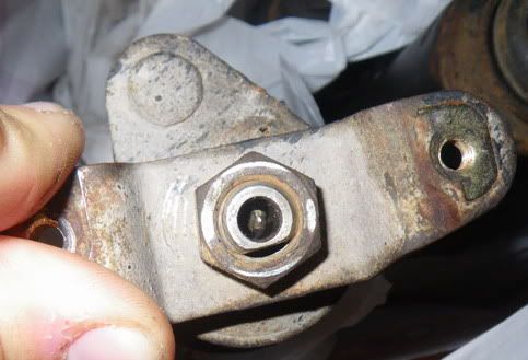
The thread on the top of the shock has a flat bit, Which only fits into the bracket one way,
The bracket has a big pin on it which go into the hole in the shock mount one the car,
When you fit the plastic motor it will line up with the pin in the top of the shock.
Hope this helps. |
|
| Back to top |
|
|
rich r
********


Age: 50
Zodiac: 
Joined: 11 Sep 2009
Posts: 5332
Location: Selby, North Yorkshire
|
| Posted: Tue Oct 19, 2010 16:19 Post subject: |
|
|
Believe me, you will be able to tell if you have 'soft' where you should have 'hard', or the other way round. On soft if you were to go round a 90 degree bend at 40kmh, you feel like it's going to roll over. On hard it stays fairly flat and controlled.
There's nothing I can see in the workshop manual that shows the mounting position unfortunately, but there are wiring diagrams if you find the system isn't working. I may be able to extract them and email them if you need them. |
|
| Back to top |
|
|
schweps
**
Age: 51
Zodiac:
Joined: 29 Nov 2009
Posts: 101
Location: Turkiye
|
| Posted: Wed Oct 20, 2010 8:26 Post subject: |
|
|
Thanks for your answer Scuftmuppet,
So the bracket will let the absorber to fit its exact place, then the front absorbers shall be interchangeable, right?
Cheers.
| Scuftmuppet wrote: |
When you fit the shocks they are handed offside and nearside,
The thread on the top of the shock has a flat bit, Which only fits into the bracket one way,
The bracket has a big pin on it which go into the hole in the shock mount one the car,
When you fit the plastic motor it will line up with the pin in the top of the shock.
Hope this helps. |
|
|
| Back to top |
|
|
Scuftmuppet
*****
Age: 60
Zodiac:
Joined: 03 Jun 2010
Posts: 981
Location: Thame Oxfordshire
|
| Posted: Wed Oct 20, 2010 8:44 Post subject: |
|
|
I think they may but not 100% sure as when i got mine they were used and the guy had marked them O/S and N/S
But im sure someone on here will let you know |
|
| Back to top |
|
|
schweps
**
Age: 51
Zodiac:
Joined: 29 Nov 2009
Posts: 101
Location: Turkiye
|
| Posted: Wed Oct 20, 2010 8:45 Post subject: |
|
|
Hi rich r,
The absorbers are at home right now and yesterday evening i made some more tests while compressing and decompressing each and sometimes as pairs.
Regarding the flat bit on the top of the thread that Scuftmuppet has mentioned, taking that flat face as a reference i found the position of the pin (with the help of a small plier) which controls the orifis (or whatever) plate to the soft mode. All 4 pins were perpendicular to that reference plane. If i change the pins position by turning them through clockwise direction about 90 degree, the absorbers become stiff. But couldn't noticed the stiffness variation between 90-180 and 270 degree positions. Anyway soft position could be areference for absorber and motor mates i guess.
Cheers.
| rich r wrote: |
Believe me, you will be able to tell if you have 'soft' where you should have 'hard', or the other way round. On soft if you were to go round a 90 degree bend at 40kmh, you feel like it's going to roll over. On hard it stays fairly flat and controlled.
There's nothing I can see in the workshop manual that shows the mounting position unfortunately, but there are wiring diagrams if you find the system isn't working. I may be able to extract them and email them if you need them. |
|
|
| Back to top |
|
|
schweps
**
Age: 51
Zodiac:
Joined: 29 Nov 2009
Posts: 101
Location: Turkiye
|
| Posted: Mon Oct 25, 2010 20:49 Post subject: |
|
|
Hi again,
Could someone please clarify this interchangeability issue of the shockers and actuators.
For example;
-Can i use front left shocker instead of the right one? Or vice versa.
-Same question for the rear shocker.
-Can i use an actuator on any of the 4 shocker?
Cheers. |
|
| Back to top |
|
|
schweps
**
Age: 51
Zodiac:
Joined: 29 Nov 2009
Posts: 101
Location: Turkiye
|
| Posted: Fri Oct 29, 2010 16:15 Post subject: |
|
|
Update.
I did some tests on the shockers to determine the position of the pin which controls the stiffness(S,M,H).
After an inspection, i noticed a flat face on the pins such like on the threaded rod (thanks to Scuftmuppet again).
According to the sketch attached, i repeated the test at 4 positions of the 4 shockers. At the test, while keeping fully opened shockers vertically, i compressed each one with my upper body weight and measured the time when they are fully collapsed.
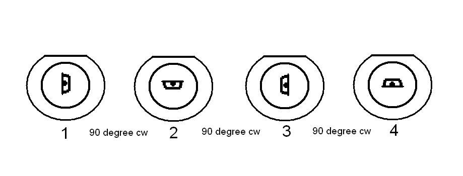
Front shocker with JI05 code;
Pos.1 (2sec) -seems to be "S" mode
Pos.2 (9sec) -seems to be "H" mode
Pos.3 (5,5sec) -seems to be "M" mode
Pos.4 (9sec) -seems to be "H" mode
Front shocker with JI10 code;
Pos.1 (2sec) -seems to be "S" mode
Pos.2 (8sec) -seems to be "H" mode
Pos.3 (5sec) -seems to be "M" mode
Pos.4 (8sec) -seems to be "H" mode
Rear shocker with JH28 code;
Pos.1 (3,5sec) -seems to be "S" mode
Pos.2 (5,5sec) -seems to be "M" mode
Pos.3 (3,5sec) -seems to be "S" mode
Pos.4 (6,5sec) -seems to be "H" mode
Rear shocker with JI02 code;
Pos.1 (3,5sec) -seems to be "S" mode
Pos.2 (5,5sec) -seems to be "M" mode
Pos.3 (3,5sec) -seems to be "S" mode
Pos.4 (7sec) -seems to be "H" mode
According to these measurements i assume that a front shocker actuator can be replaced with the other one. And rear ones as well in the same terms.
I'll try to keep this thread updated. |
|
| Back to top |
|
|
Scuftmuppet
*****
Age: 60
Zodiac:
Joined: 03 Jun 2010
Posts: 981
Location: Thame Oxfordshire
|
| Posted: Fri Oct 29, 2010 18:59 Post subject: |
|
|
Boy you really are getting involved with this 
Are you using the car between these ongoing tests and dismantling the shocks each time or
is it up on jacks 
If you phone the main dealer they will be able to tell you the info your looking for.
But keep us informed on your results  |
|
| Back to top |
|
|
schweps
**
Age: 51
Zodiac:
Joined: 29 Nov 2009
Posts: 101
Location: Turkiye
|
| Posted: Fri Oct 29, 2010 20:29 Post subject: |
|
|
Actually i baught them 2 weeks ago as used parts and before mounting them i'm trying to gather correct actuators.
According to ASA, all shockers and actuators have seperate part numbers (except rear shockers). Main dealer would answer accordingly. But i don't think so. There may be some minor differences which shouldn't really effect the working princible.
 |
|
| Back to top |
|
|
Scuftmuppet
*****
Age: 60
Zodiac:
Joined: 03 Jun 2010
Posts: 981
Location: Thame Oxfordshire
|
| Posted: Sat Oct 30, 2010 14:22 Post subject: |
|
|
Last month after buying new gas shocks without the actuators, I didnt have them fitted for long as they didnt do what they were ment to do (long story)
I then refitted the old electric ones back on and found that the front right actuator woundnt fit because the brackets and handed so i just swaped them round, They fited fine,
I would guess the actuators would be different part numbers as they will be left or right cos the wires will be entering them from different angles |
|
| Back to top |
|
|
schweps
**
Age: 51
Zodiac:
Joined: 29 Nov 2009
Posts: 101
Location: Turkiye
|
| Posted: Wed Nov 03, 2010 8:56 Post subject: |
|
|
If the reason of different part numbers, is only the cable issue you've mentioned, it would really won't bother me.
By the way Scuftmuppet, your black wheels looks great. |
|
| Back to top |
|
|
Scuftmuppet
*****
Age: 60
Zodiac:
Joined: 03 Jun 2010
Posts: 981
Location: Thame Oxfordshire
|
| Posted: Wed Nov 03, 2010 9:45 Post subject: |
|
|
Thanks Schweps Well i think my shock have gone passed there life expectancy or at least the bushings, So to hell with it, Im fitting new gas front ones today and will have a nose around at the actuators when i take them off as i am only guessing that there different part numbers is cos the wire entry.
But if they have the numbers on them it will confirm the left and right  |
|
| Back to top |
|
|
schweps
**
Age: 51
Zodiac:
Joined: 29 Nov 2009
Posts: 101
Location: Turkiye
|
| Posted: Wed Nov 03, 2010 15:27 Post subject: |
|
|
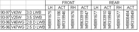
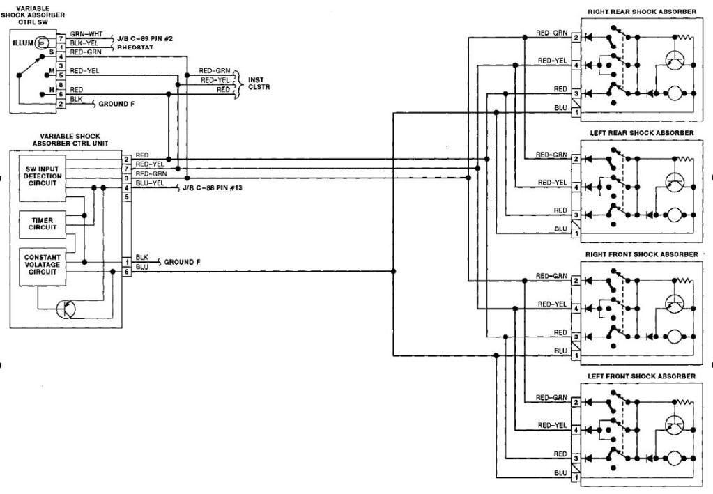
I'm pretty sure that the all 4 have different part numbers. And if it is circle shaped actuator then the part no shall be MB.... if it is rectangular shaped, part no shall be MR....
If you would take them off by the sockets, please check the cable color configuration on each socket. If they are all same then during a certain mode change by the switch all of the actuators shall behave like same. (For example they shall turn 90degree to clockwise direction)
What i understand from the wiring diagram below, confirms this i guess.
Cheers.
 |
|
| Back to top |
|
|
Scuftmuppet
*****
Age: 60
Zodiac:
Joined: 03 Jun 2010
Posts: 981
Location: Thame Oxfordshire
|
| Posted: Wed Nov 03, 2010 16:21 Post subject: |
|
|
| Yeah they all look the same in your diagram and all have the same wires going to them |
|
| Back to top |
|
|
|
|
|
You cannot post new topics in this forum
You cannot reply to topics in this forum
You cannot edit your posts in this forum
You cannot delete your posts in this forum
You cannot vote in polls in this forum
You cannot attach files in this forum
You cannot download files in this forum
|
|

